4.6. Drivers
This section provides an overview of the drivers implemented in ExaDEM, followed by a detailed description of each driver integrated into the system.
In addition, this section presents the driver-extractor tool (see Driver Extractor), which makes it possible to output field values.
4.6.1. Quick Overview of Drivers
4.6.1.1. What is a driver in ExaDEM
In ExaDEM, a driver denotes a significant shape, such as walls, cylinders, or other geometric forms, which are treated differently from particles due to their unique characteristics. While the ExaDEM framework has been optimized and parallelized to effectively handle particles and polyhedra of comparable scales, drivers necessitate special treatment owing to their distinct properties. To accommodate multiple drivers in a simulation, ExaDEM offers flexibility through the creation of a drivers list. This feature allows users to include any number of drivers required to define boundary conditions and obstacles within the simulation environment.
The current implementation of ExaDEM includes a variety of drivers, each serving specific purposes within the simulation framework. The detailed list of implemented drivers is provided in the following table:
Name |
Driver Type |
Operator Name |
|---|---|---|
Cylinder |
|
|
Wall / Surface |
|
|
Ball / Sphere |
|
|
RShape |
|
|
Undefined |
|
no operator |
Note
When adding a driver to the simulation in ExaDEM, it is essential to define a contact parameter list specific to the driver within the compute_contact_interaction operator.
4.6.1.2. Common Driver Parameters
Drivers share common parameters contained in the Driver_params class. These parameters are mainly used in the time integration scheme to detect the type of displacement. In the tables below, we describe the types of motion available by drivers as well as a list of motions available on the driver:
Motion type |
Description |
|---|---|
|
Stationary state with no translational motion, allowing rotations of Drivers. |
|
Linear movement type, straight-line motion at constant velocity |
|
Movement influenced by compressive forces, depending on driver type. |
|
Linear motion driven by constant acceleration, incorporating the effects of the sample’s resultant force. |
|
General movement caused by applied forces. Act likes a particle (R-shape). |
|
Linear movement combined with compressive forces. |
|
Motion defined by precomputed or tabulated data. |
|
Oscillatory or vibratory motion, typically mimicking a shaking mechanism. |
|
Oscillatory swinging around a suspension point (pendulum-like). |
|
Impose a velocity or angular velocity field defined by a user-specified analytical expression. This option use the library tinyexpr: Github |
Motion Type |
|
|
|
|
|
|
|
|
|
|
|---|---|---|---|---|---|---|---|---|---|---|
Cylinder |
✔ |
✘ |
✘ |
✘ |
✘ |
✘ |
✘ |
✘ |
✘ |
✘ |
Surface |
✔ |
✔ |
✘ |
✘ |
✘ |
✔ |
✘ |
✔ |
✔ |
✘ |
Ball |
✔ |
✔ |
✔ |
✘ |
✘ |
✘ |
✔ |
✘ |
✘ |
✘ |
Stl Mesh |
✔ |
✔ |
✘ |
✔ |
✘ |
✔ |
✔ |
✔ |
✘ |
✔ |
For all these types of movement, the drivers adopt a velocity Verlet integration time scheme. Below is a summary table showing how positions, forces, or velocities are calculated according to the type of movement.
with \(P\) the driver position, \(V\) the driver velocity.
with \(V\) the driver velocity, \(M_{vector}\) the motion vector, and \(C_{velocity}\) the value of the [constant] velocity.
For spheres (or Ball), we adapt the scalar radius value (radius (\(R\)), \(R_{velocity}\), \(R_{acceleration}\)):
with \(S\), the driver surface, \(m_{system}\) the mass of the system, and math:damprate the damprate (TODO complete).
with \(F\) the driver forces, \(F_{driver}\) the sum of the forces applied to the driver by the particles, \(C_F\) the value of the [constant] force, and \(M_{vector}\) the motion vector.
with \(F\) the driver forces and \(F_{driver}\) the sum of the forces applied to the driver by the particles.
with \(F\) the driver forces, \(V\) the driver velocity, \(S\), the driver surface, \(damprate\) the damprate (TODO complete), and \(M_{vector}\) the motion vector.
with \(C\) the driver center, \(C_{initial}\) the initial driver center at \(T\) = t - motion_start_threshold, math:N_{shaker} the shaker normal vector, math:V the driver velocity, \(A\) the signal amplitude, and \(\omega\), the signal frequency.
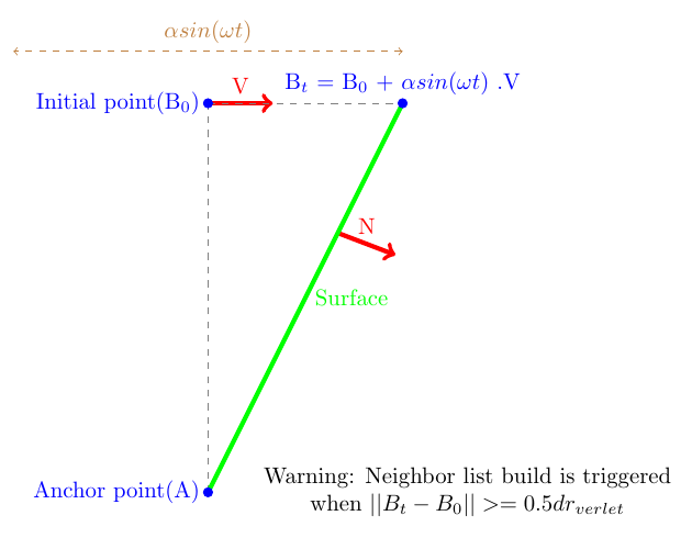
with \(B_0\) the initial position, \(B_t\) the current position at \(T\) = t - motion_start_threshold, math:D the swing normal vector, math:V the driver velocity, \(A\) the signal amplitude, \(\omega\), the signal frequency, \(A\), the anchor point (A is invariant and always intersect the surface), \(N\) the normal of the surface (if it’s a surface) or the new direction of the object.
\[ \begin{align}\begin{aligned}V = Fomula(t)\\V_{rot} = Formula(t)\end{aligned}\end{align} \]
with math:V the driver velocity and math:V_rot the angular driver velocity. Formula are defined in the struct Driver_expr (expr) in the slot params.
And keywords:
motion_vector: \(M_{vector}\), slotparams
const_vel: \(C_{velocity}\), slotparams
const_f: \(C_F\), slotparams
damprate: \(damprate\), slotparams
amplitude: \(A\), slotparams
omega: \(\omega\), slotparams
shaker_dir: \(N_{shaker}\), slotparams
pendulum_anchor_point: \(Anchor\), slotparams
pendulum_initial_position: \(B_0\), slotparams
pendulum_swing_dir: \(D\), slotparams
4.6.1.3. Add a Driver To Your Simulation
In ExaDEM, drivers are managed differently depending on whether spheres or polyhedra are used in the simulation. Forces are computed per interaction for polyhedra, while forces are computed and summed per sphere body:
Using spheres, a special contact force is added to handle interactions with drivers in the
contact_force_driveroperator.Using polyhedra, special interactions (described in the Polyhedra section) are added to the interaction lists. Additionally, you need to specify your driver list in the list of operators called
setup_drivers, which is integrated into the defaultExaDEMexecution. It’s crucial to specify an ID for each driver. If you create a second driver with an already used ID, it will overwrite the previous driver configuration.
In the following sections, we provide brief descriptions of available drivers. Please note that a test case is defined for each driver in the example directory.
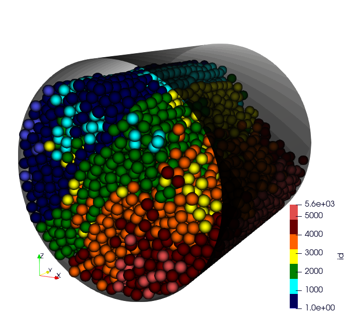
4.6.2. Rotating Drum / Cylinder
The rotating drum or cylinder driver represents an infinite cylinder rotating along a specified axis. It is defined by parameters including its middle, velocity, axis, and angular velocity.
Operator name:
register_cylinderDescription: This operator adds a cylinder to the drivers list.
Parameters:
id: Driver index
state: Current cylinder state, default is {radius: REQUIRED, axis: REQUIRED, center: REQUIRED, vel: [0,0,0], vrot: [0,0,0], rv: 0, ra: 0}. You need to specify the radius and center.
params: List of params, motion type, motion vectors …. Default is { motion_type: STATIONARY}.
YAML example:
- register_cylinder:
   id: 0
   state: {center: [2.5, 2.5, 2.5], axis: [1, 0, 1], radius: 4}
   params: { motion_type: STATIONARY }
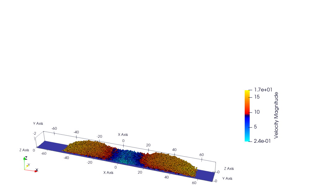
4.6.3. Wall / Surface
The wall or surface driver represents an infinite wall within the simulation environment. It is defined by parameters including its normal vector, offset, and velocity. Please note that currently, no angular velocity is defined for this driver.
Operator name:
register_surfaceDescription: This operator adds a surface/wall to the drivers list.
Parameters:
id: Driver index
state:
params:
4.6.3.1. STATIONARY mode
- register_surface:
   id: 0
   state: {normal: [0,0,1], offset: -0.5}
   params: { motion_type: STATIONARY }
4.6.3.2. LINEAR_MOTION mode
- register_surface:
   id: 4
   state: { normal: [1,0,0], offset: 11}
   params: { motion_type: LINEAR_MOTION, motion_vector: [-1,0,0], const_vel: 2.5 }
This example is available at: exaDEM/example/spheres/rigid-surface/rigid_surface_linear_motion.msp
Note
motion vector can only be equal to normal and -normal.
4.6.3.3. LINEAR_COMPRESSIVE_MOTION mode
- register_surface:
   id: 4
   state: { normal: [1,0,0], offset: 11, surface: 144}
   params: { motion_type: LINEAR_COMPRESSIVE_MOTION, motion_vector: [1,0,0], sigma: 0.5, damprate: 0.999 }
This example is available at: exaDEM/example/spheres/rigid-surface/compression_wall.msp
This example is available at: exaDEM/example/polyhedra/rigid_surface/rigid_surface_compression_motion.msp
Note
If you have chosen the “LINEAR_COMPRESSIVE_MOTION” mode, you will need to define the value of the wall surface.
The motion_vector is set to normal.
When σ > 0 and the surface is free of external forces, the wall displaces in the direction opposite to the surface normal.
4.6.3.4. SHAKER mode
- register_surface:
   id: 2
   state: {normal: [0,0,1], offset: -1}
   params:
      motion_type: SHAKER
      amplitude: 0.5
      omega: 1e1
      motion_start_threshold: 3.0
      motion_end_threshold: 8.0
4.6.3.5. PENDULUM_MOTION mode
- register_surface:
   id: 3
   state: { normal: [1,0,0], offset: -1} # ignored
   params: { motion_type: PENDULUM_MOTION, amplitude: 3, omega: 4, pendulum_anchor_point: [-1,5,-1], pendulum_initial_position: [-1, 5, 11], pendulum_swing_dir: [1, 0, 0] }
See example: example/spheres/rigid-surface/rigid_surface_pendulum_motion.msp
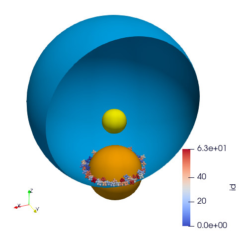
4.6.4. Ball / Sphere
The ball or sphere driver represents a spherical object within the simulation environment. It is defined by parameters including its center, velocity, and angular velocity. This driver can be utilized as a boundary condition or obstacle in the simulation.
Operator name:
register_ballDescription: This operator adds a ball / sphere (boundary condition or obstacle) to the drivers list.
Parameters:
id: Driver index
state: Current ball state, default is {radius: REQUIRED, center: REQUIRED, vel: [0,0,0], vrot: [0,0,0], rv: 0, ra: 0}. You need to specify the radius and center.
params: List of params, motion type, motion vectors …. Default is { motion_type: STATIONARY}.
Note
ra is the “radius acceleration” and rv the “radius velocity” used during the radial compression, i.e. shrinking or stretching the radius of a ball until the desired pressure is reached between the ball and the particles inside. This requires the motion type
COMPRESSIVE_FORCE.If the motion type is
LINEAR_MOTION, the velocity (vel) is computed from motion_vector and const_vel.If the motion type is
COMPRESSIVE_FORCE, the velocity (vel) is set to 0.
4.6.4.1. STATIONARY mode
YAML example:
- register_ball:
   id: 2
   state: {center: [2,2,-20], radius: 7}
   params: { motion_type: STATIONARY }
See: exaDEM/example/spheres/ball/driver-ball-stationary.msp
4.6.4.2. LINEAR MOTION mode
- register_ball:
   id: 1
   state: {center: [30,2,-10], radius: 8}
   params: { motion_type: LINEAR_MOTION , motion_vector: [-1,0,0], const_vel: 0.5}
See: exaDEM/example/spheres/ball/driver-ball-linear.msp
4.6.4.3. COMPRESSIVE_FORCE mode
- register_ball:
   id: 0
   state: {center: [0,0,0], radius: 11}
   params: {motion_type: COMPRESSIVE_FORCE , sigma: 1.0, damprate: 0.999}
See: exaDEM/example/spheres/ball/driver-ball-radial-stress.msp
4.6.4.4. TABULATED mode
- register_ball:
   id: 0
   state: {center: [0,0,0], radius: 7}
   params:
      motion_type: TABULATED
      time: [0, 25, 50, 75]
      positions: [[-20,0,-20], [20,0,-20], [20, 0, -15], [-20, 0, -15]]
See: exaDEM/example/spheres/ball/driver-ball-tabulated.msp
4.6.5. RShape / Polyhedron
The RShape driver is constructed from a .stl (Stereolithography) or a .shp (Shape file) file to create a mesh of faces. This approach enables the rapid setup of complex geometries within the simulation environment. It’s important to note that faces in a RShape driver are processed as a sphere polyhedron, meaning a small layer is added around each face.
Operator name:
register_stl_mesh/register_rshapeDescription: This operator adds a “RShape” to the drivers list.
Parameters:
id: Driver index
filename: Input filename (.stl or .shp)
minskowski: Minskowski radius value
binary: Define if the stl file is ascii or binary, default is false. Ignored if the format file is a .shp.
scale: Define the scale factor of applied to the shape, default is 1.
deform: Define the non-uniform deformation factors along x, y, and z axes. Format is [x, y, z]. Values must be strictly positive. Default is [1, 1, 1].
state: Define the center, velocity, angular velocity and the orientatation. Default is: state: {center: [0,0,0], vel: [0,0,0], vrot: [0,0,0], quat: [1,0,0,0]}.
params: List of params, motion type, motion vectors …. Default is { motion_type: STATIONARY}.
YAML examples:
4.6.5.1. STATIONARY mode
- register_stl_mesh:
   id: 0
   binary: false
   filename: mesh.stl
   minskowski: 0.001 m
   params: {motion_type: STATIONARY}
4.6.5.2. LINEAR_MOTION mode
- register_rshape:
   id: 0
   state: {center: [0.4,0,0]}
   params: { motion_type: LINEAR_MOTION, motion_vector: [-1,0,0], const_vel: 0.5 }
   filename: mesh.shp
   minskowski: 0.001 m
4.6.5.3. TABULATED mode
- register_stl_mesh:
   id: 0
   state: {}
   params:
      motion_type: TABULATED
      time: [0, 1, 1.5, 2]
      positions: [[0.4, 0, 0], [-1, 0, 0], [0.4, 0, 0], [0.4, 0, 0]]
   filename: mesh.stl
   minskowski: 0.001 m
4.6.5.4. LINEAR_FORCE_MOTION mode
- register_stl_mesh:
   id: 1
   filename: piston_haut.stl
   scale: 0.5002
   minskowski: 0.001
   state: { center: [0.0, 0.0, 9.], vel: [0,0,-0.025], quat: [1,0,0,0], mass: 1}
   params: { motion_type: LINEAR_FORCE_MOTION, motion_vector: [0,0,-1], const_force: 100 }
Note
You need to define the mass of your driver.
4.6.5.5. LINEAR_COMPRESSIVE_MOTION mode
- register_stl_mesh:
   id: 1
   filename: piston_haut.stl
   scale: 0.5002
   minskowski: 0.001
   state: { center: [0.0, 0.0, 9.], vel: [0,0,-0.025], quat: [1,0,0,0], mass: 1, surface: 1.6146970415e+02}
   params: { motion_type: LINEAR_COMPRESSIVE_MOTION, motion_vector: [0,0,-1], sigma: 0.5, damprate: 0.5 }
Note
You will need to define the mass and the surface of your driver. If you don’t specify a surface, exaDEM will propose to you a value corresponding to the sum of the face surfaces composing the RShape driver.
4.6.5.6. SHAKER mode
- register_rshape:
   id: 0
   minskowski: 0.1
   filename: shaker.stl
   binary: true
   state: {center: [0,0,0] }
   params: { motion_type: SHAKER, amplitude: 5, omega: 2 , shaker_dir: [0,1,0] , motion_start_threshold: 10 }
This example is available here: exaDEM/example/spheres/shaker/shaker_stl.msp
4.6.5.7. EXPRESSION mode
This example is available here (RSA plugins is required): exaDEM/example/spheres/stl-mesh/tore_expression_motion.msp
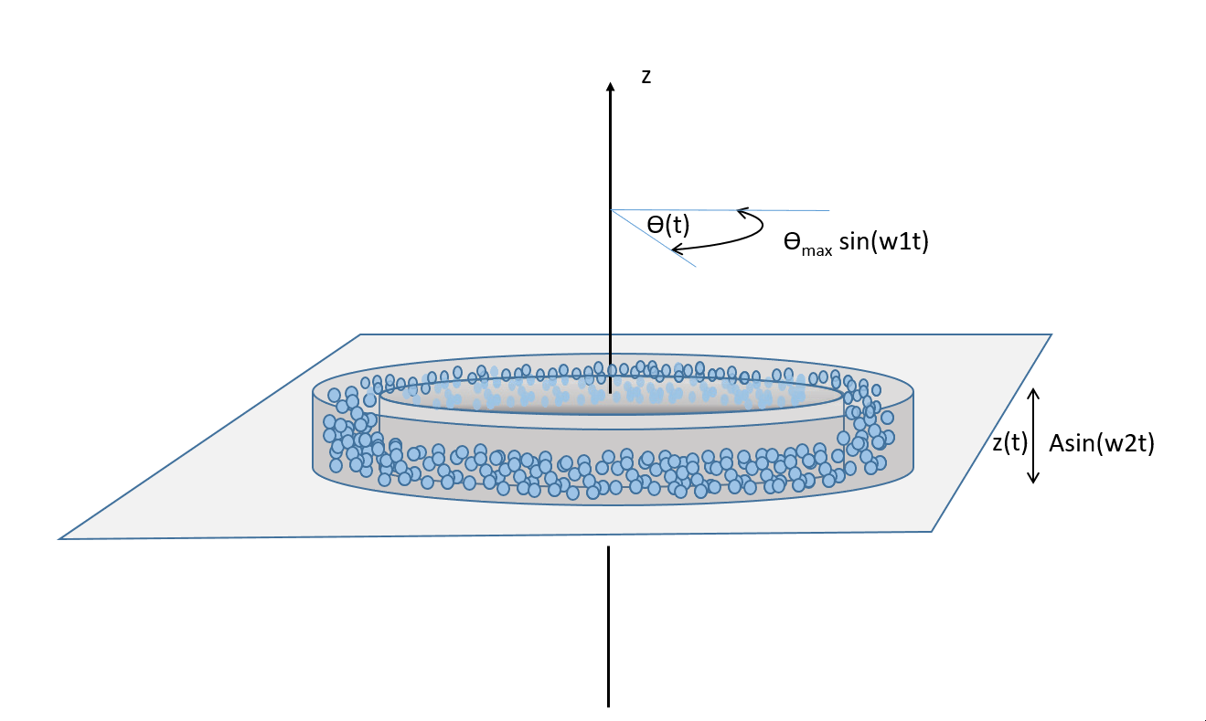
- register_stl_mesh:
   id: 0
   filename: tore.stl
   minskowski: 0.01
   state: { }
   params:
      motion_type: EXPRESSION
      expr:
         vz: 2.5 * cos( 10 * t)
         vrotz:  0.5 * cos(20 * t)
   binary: true
Example to impose moment:
- register_stl_mesh:
   id: 0
   filename: pale2.stl
   minskowski: 0.01
   binary: true
   state:
      vrot: [0,0,0]
      center: [2.5,2.5,2]
      quat: [0,-0.707107,-0.707107,0]
      mass: 49.0454
      inertia: [77.238167282, 388.401803042, 344.515979122]
   params:
      motion_type: EXPRESSION
      expr:
         momx: 0
         momy: 0
         momz: 5
This example is available at: exaDEM/example/polyhedra/imposed_driver_moment/driver_expr_mom.msp. It corresponds to the example in the following section.
Another example is available at: exaDEM/example/spheres/cylinder_stl and is a funny variant of Rotating drum simulation .
4.6.5.8. Applying a Constant Moment with Sample Retroaction
It is possible to apply a constant moment while accounting for the retroaction exerted by the sample onto the driver. To enable this behavior, the driver definition must include the following physical properties:
center: The rotation center of the driver.
inertia: The rotational inertia of the driver.
mass: The mass of the driver.
As with angular velocity control, this mechanism does not fall under
the motion_type category.
Note
The applied moment is restricted to the direction defined in the
moment slot. Only the component aligned with this direction is applied.
YAML example:
setup_drivers:
  - register_stl_mesh:
     id: 0
     filename: pale2.stl
     minskowski: 0.01
     binary: true
     state: { vrot: [0,0,0], center: [2.5,2.5,2], quat: [0,-0.707107,-0.707107,0] , mass: 49.0454, inertia: [77.238167282, 388.401803042, 344.515979122], moment: [0,0,1] } # vrot: rad.s-1 normalement
     params: { motion_type: STATIONARY }
These examples are available at:
[Right]:
example/polyhedra/imposed_driver_moment/driver_counter_mom.msp[Left]:
example/polyhedra/imposed_driver_moment/driver_applied_mom.msp
4.6.6. Modification of a Driver’s Motion Type
This feature allows changing the motion type of a driver during a simulation.
Each driver is identified by an id, assigned when the driver is registered.
To enable motion changes, you can add one or more calls to modify_motion inside the
driver_motion_policy YAML block (nop by default).
Operator name: modify_motion
Parameters:
id: Index of the target driver.motion: Dictionary defining the new motion parameters (motion type, motion vectors, etc.). Example:{ motion_type: STATIONARY }.time: Simulation time at which the motion type should be changed.display: Iftrue, prints details about the updated motion type (default:false).
YAML Example:
driver_motion_policy:
  - modify_motion:
      id: 0
      time: 0.5
      motion: { motion_type: LINEAR_COMPRESSIVE_MOTION, motion_vector: [1,0,0], sigma: 5, damprate: 0.999 }
      display: true

  - modify_motion:
      id: 0
      time: 1.5
      motion: { motion_type: STATIONARY }

  - modify_motion:
      id: 0
      time: 2.5
      motion: { motion_type: LINEAR_COMPRESSIVE_MOTION, motion_vector: [1,0,0], sigma: 5, damprate: 0.999 }

  - modify_motion:
      id: 0
      time: 4.0
      motion: { motion_type: LINEAR_MOTION, motion_vector: [1,0,0], const_vel: 3 }
Example available: exaDEM/example/polyhedra/rigid_surface/rigid_surface_modify_motion.msp
4.6.7. I/O Drivers
An input/output system has been implemented primarily for drivers performing movements, such as a rigid surface compressing a sample or a blade rotating around an axis.
The drivers’ output is automatically triggered when the user sets the global variable: simulation_dump_frequency. This command also allows particles and interactions to be stored in a separate file. The drivers are then saved in a file located at ExaDEMOutputDir/CheckpointFiles/driver_%010d.msp, containing the drivers’ information. In the case of an RShape driver, a shp file is added to the ExaDEMOutputDir/CheckpointFiles/ directory, which contains the geometry of the RShape. To restart the driver along with your simulation, simply include the .msp file containing the setup_driver operator block at the beginning of your restart file.
YAML example:
grid_flavor: grid_flavor_dem
includes:
  - config_spheres.msp
  - ExaDEMOutputDir/CheckpointFiles/driver_0000040000.msp
global:
  simulation_dump_frequency: 10000
Similarly, ExaDEM saves RShape drivers each time a Paraview output is generated by setting the global variable: simulation_paraview_frequency. The RShape driver is then translated and oriented correctly in the ExaDEMOutputDir/ParaviewOutputFiles/ directory as shape_name_iteration.vtk.
Another feature displays the driver summary. To do this, use the print_drivers operator, which is called by default when initializing an exaDEM simulation.
Operator name:
print_driversDescription: This operator prints drivers.
YAML example:
- print_drivers
Output example:
==================== Driver Configurations =======================
===== Summary
Drivers Stats
Number of drivers: 3
Number of Cylinders: 1
Number of Surfaces: 0
Number of Balls: 0
Number of Stl_meshs: 2
Number of Undefined Drivers: 0
===== List Of Drivers
Driver [0]:
Driver Type: RSHAPE
Name   : base
Center : 0,0,-20
Vel    : 0,0,0
AngVel : 0,0,0
Quat   : 1 0 0 0
Number of faces    : 52
Number of edges    : 150
Number of vertices : 100
Driver [1]:
Driver Type: Cylinder
Radius: 25
Axis  : 1,1,0
Center: 0,0,0
Vel   : 0,0,0
AngVel: 0,0,0
Driver [2]:
Driver Type: RSHAPE
Name   : palefine
Center : 0,0,1.5
Vel    : 0,0,-0.0174
AngVel : 0,0,-0.004
Quat   : 1 0 0 0
Number of faces    : 25952
Number of edges    : 77856
Number of vertices : 31647
=================================================================
4.6.8. Driver Extractor
The driver extractor tool is used to retrieve specific quantities related to drivers in an output file. To do so, trackers are added and identified by the driver ID and the field that should be recorded.
The use of this tool is integrated into the default exaDEM workflow; however, if no tracker has been defined, it remains inactive and performs no operation.
4.6.8.1. Tracker Dictionary
The driver extractor provides a set of predefined trackable fields that can be recorded for each driver during a simulation. These fields correspond to the main kinematic and dynamic quantities associated with the driver state. Each field is identified by a string key and associated with a specific data type.
The full list of available trackable fields is given below:
Name |
Type |
Description |
|---|---|---|
type |
int |
Driver type identifier |
rx |
double |
Position component along the x-axis |
ry |
double |
Position component along the y-axis |
rz |
double |
Position component along the z-axis |
vx |
double |
Linear velocity component along the x-axis |
vy |
double |
Linear velocity component along the y-axis |
vz |
double |
Linear velocity component along the z-axis |
vrotx |
double |
Angular velocity component around the x-axis |
vroty |
double |
Angular velocity component around the y-axis |
vrotz |
double |
Angular velocity component around the z-axis |
fx |
double |
Force component along the x-axis |
fy |
double |
Force component along the y-axis |
fz |
double |
Force component along the z-axis |
momx |
double |
Torque component around the x-axis |
momy |
double |
Torque component around the y-axis |
momz |
double |
Torque component around the z-axis |
4.6.8.2. Adding a driver tracker
Trackers are used by the driver extractor to record specific fields associated with selected drivers during a simulation. Each tracker is defined by a driver identifier (id) and a list of fields to be extracted for that driver.
If no tracker is registered, the driver extractor remains inactive and produces no output.
Configuration is done through the register_driver_extractor operator as shown below:
setup_drivers:
  ...

input_data:
  - register_driver_extractor:
     trackers:
       - id: 2
         fields: [vroty, fx, fy, fz, momy]
       - id: 0
         fields: [fy]
       - id: 1
         fields: [fy]
      verbosity: true
The id field corresponds to the unique identifier of the driver. The fields list specifies which quantities (see Trackable fields section) will be recorded for this driver.
When verbosity is enabled, the extractor prints additional information about the registered trackers during initialization, which can be useful for debugging and verification.
In addition, exaDEM displays the driver extractor after the initialization step:
======= Driver Extractor ========
Tracked Driver Id: 2 | Fields: [ vroty fx fy fz momy ]
Tracked Driver Id: 0 | Fields: [ fy ]
Tracked Driver Id: 1 | Fields: [ fy ]
=================================
4.6.8.3. Output format
The driver extractor writes its results to a single text file located at:
DriverExtractor/data.txt
This file contains a tabular time history of all requested tracker fields. Each column follows the naming convention:
field_driverId
where field is the tracked quantity name and driverId is the identifier of the corresponding driver.
The first column of the file is always the physical simulation time (time), which is included automatically regardless of the registered trackers.
An example of the generated output file is shown below:
time vroty_2 fx_2 fy_2 fz_2 momy_2 fy_0 fy_1
0.000500 0.250000 0.000000 0.000000 0.000000 0.000000 0.000000 0.000000
0.005000 0.250000 0.000000 0.000000 0.000000 0.000000 0.000000 0.000000
0.010000 0.250000 0.000000 0.000000 0.000000 0.000000 0.000000 0.000000
0.015000 0.250000 0.000000 0.000000 0.000000 0.000000 0.000000 0.000000
0.020000 0.250000 0.000000 0.000000 0.000000 0.000000 0.000000 0.000000
...
9.980000 0.250000 -5.379081 -0.862643 -81.987323 -85.784585 19.196276 -17.884607
9.985000 0.250000 -8.693555 -0.686199 -81.536812 -70.726712 20.135705 -16.727052
9.990000 0.250000 -7.350304 -0.607916 -82.138185 -77.959601 20.321566 -17.626298
9.995000 0.250000 -9.204748 -0.436030 -82.881255 -78.163145 21.723900 -17.480386
10.000000 0.250000 -10.570360 -0.150192 -83.541703 -75.363659 21.616698 -16.890325
Note
Each registered tracker contributes one or more columns to the output file.
Columns are ordered according to the registration sequence of trackers and fields.
Missing or inactive drivers will result in zero-valued or unchanged outputs depending on the simulation state.
The time column corresponds to the physical simulation time, not the iteration index.
4.6.9. Advanced Operators
4.6.9.1. Update Grid For RShape Driver
The purpose of this operator is to project the RShape (vertices, edges, and faces) onto the cells making up the exaDEM grid in order to speed up the search for interactions. Each grid cell is then assigned a set of vertices, edges, and faces that are potentially in contact with the cell’s particles.
Operator name:
grid_rshape_driverDescription: Update the list of information for each cell regarding the vertex, edge, and face indices in contact with the cell in a RShape driver.
Parameters:
force_reset: Force to rebuild grid.
Note
[1] This operator only projects the RShape driver onto the grid making up the MPI process subdomain. If the subdomain changes, the update must be forced (force_reset=0). [2] If the RShape is stationary (v= null, vrot=null), the grid is not updated. This speeds up calculations when the RShape driver has many elements.
YAML example:
- compute_driver_vertices:
   force_reset: true
4.6.9.2. Compute Driver Vertices
This operator is used to update the vertex positions of operators with vertices. For the moment, this operator is only used for RShape drivers and to fill in the vertices field.
Operator name:
compute_driver_verticesDescription: This operator calculates new vertex positions.
Parameters:
force_host: Force computations on the host
Note
For GPU performance reasons, you may decide not to update the GPU data directly, knowing that it will be used to build the CPU interaction list.
YAML example:
- compute_driver_vertices:
   force_host: false
4.6.9.3. Check Driver Displacement
This operator detects if a driver has moved more than 1/2 of the Verlet radius. This operator works in combination with the backup_driver operator to store driver data at the iteration when the interaction lists have been recalculated.
In the case of a sphere, we test the distance between the two centers.
In the case of a RShape, we check the displacement of all vertices.
In the case of a cylinder, this option is disabled.
In the case of a wall, we look at the difference between the offset values.
Currently, for the GPU version, these tests are carried out on the CPU, except for the detection of stl meshes, which requires a reduction operation. Operator characteristic:
Operator name:
driver_displ_overDescription: It computes the distance between each particle in grid input and its backup position in backup_dem input. It sets result output to true if at least one particle has moved further than threshold.
Parameters:
threshold: Defined by the simulation (deduced from rcut_inc)
YAML example:
- driver_displ_over